11.The current waveform in a pure resister of 10 ohm is shown in Fig Q.11. The power dissipated in the resister is

Fig Q.11
A) 7.29W
B) 270 W
C) 135 W
D) 52.4 W
12. The circuit shown in Fig. Q. 12 will resonate at all frequencies, if

Fig Q.12
A) R=√(»C/L)
B) R=√(L/C)
C) C=L/R
D) L=1/RC
13. In the coupled circuit shown in Fig 13 the maximum value of the voltage induced, V2 is

Fig Q.13
A) 8.8 V
B) 9.2 V
C) 10.7 V
D) 12.5 V
14.The impedances z1,z2 and z3 are delta connected to a 3 phase symmetrical 400 V, 50 Hz supply with phase sequence ABC as shown in Fig Q14. When z1=(10+j0)ohm, z2=(8+j6)ohm and z3=(5-j5)ohm the line current IB is

Fig Q.14
A) 95.75 |__-8.790 A
B) 35.2 |__120.460 A
C) 78.37 |__-168.40 A
D) 52.78 |__72.60 A
15. For the block diagram shown in Fig Q.15 the overall transfer function C(s)/R(s) is given by,

Fig Q.15
A) -1
1+G
B) -1
1-G
C) 2G-1
1-G
D) 2G+1
1+G
16. The loop transfer function G(s)/H(s) corresponding to the polar plot shown in Fig Q. 16 is
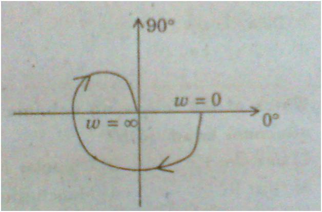
Fig Q.16
A) K
s(1+T1s)(1+T2s)
B) K
s(1+T1s)(1+T2s) (1+T3s)
C) K
(1+T1s)(1+T2s) (1+T3s)
D) K
(1+T1s)(1+T2s)
17.The driving point impedance of the network shown in Fig Q.17 is

Fig Q.17
A) (3/4)s+(3/2s)
B) (4/3)s+(3/2s)
C) (4/3)s+(2/3s)
D) (4/3)s+(2/3s)
18. The state equation in matrix form for the network shown in Fig Q.18 is

Fig Q.18
19. The voltage transfer ratio of the network shown in Fig. Q. 19 is

Fig Q.19
A)1+RCs
B)1/(1+RCs)
C)s/(1+RCs)
D) R(1+Cs)
20.The short-circuit admittance matrix of the network shown in Fig.Q. 20 is given as

Fig Q.20

Answer: 11)D 12)B 13)D 14)C 15)C 16)C 17)C 18)A 19)B 20)A
0 comments:
Post a Comment